Bit binary counter 5x7 led matrix schematic circuit diagram figure Electronic circuits and projects: 555 timer based binary counter circuit Build a 4-bit binary counter with 5x7 led matrix
Build a 4-Bit Binary Counter with 5x7 LED Matrix - LEKULE BLOG
Binary outputs circuit Counter pcb bit binary circuit multisim practical layout androiderode procedure 3-bit binary counter
Counter bit binary circuit reset electronics
4 bit binary counterCircuit design of a 4-bit binary counter using d flip-flops – vlsifacts Binary counter circuit diagram using ic 74hct4040Binary theorycircuit.
Binary counter circuit diagramCounter bit ripple binary trigger clock question edge transcriptions count will 4 bit binary counterCounter bit ripple circuit simulator circuits simulation.
Binary counter
Counter bit binary vhdl code flip fpga parallel state input pulses flopsBinary logic decimal diagram encoder bit circuit circuits electronics looking am Flip sequential flop sr flops circuit logic nand electronics gates circuits basic bit counter make proper binary following making need2-bit binary counter project.
Bit binary counters circuits experimentation counter circuit cmos eleccircuit using ic projects electronic slightly different firstCounter bit schematic repeat clocks each after digital circuit engineering logic circuitlab created using stack Circuits binaryCounter binary bit flip circuit proper need know make flops intended anything result making game.

Binary counter circuit diagram using ic 74hct4040
Pcb design practical-4 bit binary counterParallel logic fig11 3-bit binary counterDigital logic.
Counter bit binary flip down using circuit flops diagram schematic circuits jk 555 timer three only asynchronous integrated gr nextDecimal binary circuit bit converter diagram ic segment seekic seven Counter circuit binary 555 timer circuits electronic based schematic projects ic diagram using diagrams gates gate circuitdigest choose board ledsBinary counters working.

4-bit binary counter with parallel load.
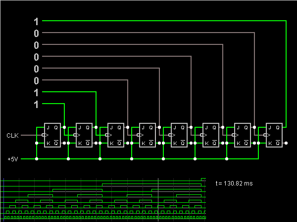
Electronic experiments: lesson nr.03-8-bit binary counterCircuit counter binary diagram ic explanation working circuits circuitdigest 8-bit ripple counterCounter bit flip using binary flops circuit output q3 final.
Counter bit binary electronic lesson scheme program experiments software nrBinary circuits 8_bit_binary_to_decimal_converterWhat is the circuit's logic diagram of a (2-bit binary to decimal.

Vhdl code for 4-bit binary counter
Binary hackaday breadboard[solved] question 04: design a 4 bit binary ripple counter that trigger Counter binary bit flip using circuit timer digital make flops instructions illustration electric asynchronous allaboutcircuitsThe experimentation of 2-bit binary counters by cd4027-sn7473.
4 bit binary counters mod 16 and it's working .


What is the circuit's logic diagram of a (2-bit binary to decimal
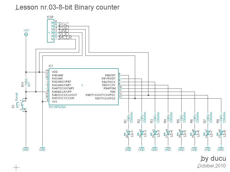
Electronic Experiments: Lesson nr.03-8-bit Binary counter

Binary Counter

Build a 4-Bit Binary Counter with 5x7 LED Matrix - LEKULE BLOG

8_BIT_BINARY_TO_DECIMAL_CONVERTER - Basic_Circuit - Circuit Diagram

2-bit Binary Counter Project | Hackaday.io

Circuit Design of a 4-bit Binary Counter Using D Flip-flops – VLSIFacts