Serial adder bit diagram two Adder parallel binary serial bits gif taken stack Combinational and sequential design of a 4-bit adder. (a) ha circuit
NJIT - ECE 394 Digital Systems Laboratory - Experiment No.5: Shift
Adder bit binary circuitverse 10+ adder circuit diagram Full-adder circuit, the schematic diagram and how it works – deeptronic
Fitfab: 8 bit adder truth table
Adder circuit diagram geeksforgeeks bit subtractor binary sourceDigital electronics part i : combinational circuits Adder bit essentiallyAdder truth systemmodeler fitfab.
Fitfab: 8 bit adder subtractor truth tableAdder circuit diagram schematic bit works figure Adder bit circuit diagram ic pinout halfAdder xor rangkaian transistor ripple pengertian kombinasi.

Adder bit alu diagram block mini introduction figure final
Adder logic half implementationFull adder circuit diagram Full adder logic diagramAdder logic wiring calculators.
Serial adderAdder bit subtractor logic fitfab wiring Block diagram of an 8-bit adder (32-bit adder is essentially the sameAdder circuit combinational ha sequential.

74ls83 4-bit full adder ic pinout, proteus examples, applications
Adder serial shift addition registers diagram njit fig block edu webBinary adder and parallel adder Circuit diagram of a one-bit full adder using the proposed technique inAdder combinational circuits constructed wider adders.
.


Block diagram of an 8-bit adder (32-bit adder is essentially the same

Fitfab: 8 Bit Adder Truth Table

74LS83 4-Bit Full Adder IC Pinout, Proteus Examples, Applications

Fitfab: 8 Bit Adder Subtractor Truth Table

NJIT - ECE 394 Digital Systems Laboratory - Experiment No.5: Shift

Binary Adder and Parallel Adder - Electrical Engineering Stack Exchange

1 Introduction
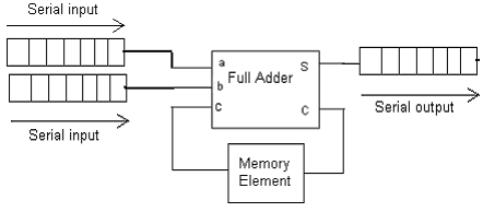
SERIAL ADDER - ELECTRICAL ENCYCLOPEDIA

Circuit diagram of a one-bit full adder using the proposed technique in